A die-cut EMI shielding part is a conductive part, made from metal foil, conductive foam or conductive tape, cut to the shape of a housing or board to close the path for electromagnetic interference. How well it shields depends on the material, but also on converting decisions: the conduction path of the adhesive, the cut geometry, the compression once assembled and the metal pairing at the contact.
Have your shielding part reviewed
What an EMI shielding part has to do
Electromagnetic compatibility (EMC) is, in TE Connectivity’s EMC documentation, the ability of a device to work properly in its electromagnetic environment without disturbing the equipment around it. In the European Union, equipment placed on the market must comply with the EMC Directive 2014/30/EU. Part of the problem is solved on the circuit board, through layout and filtering. The rest is solved at the enclosure, and that is where a die-cut part comes in.
Shielding effectiveness is expressed in decibels. It compares the field reaching the shield with the field coming out the other side: 20 log (incident field / transmitted field). Some of the energy is reflected at the surface and some is absorbed in the thickness. At higher frequencies, absorption dominates.
A well-designed metal enclosure blocks most of it. Its weak points are its openings, such as the joint between cover and base or the cut-outs for connectors. EMC engineer Ron Brewer points out that seams are usually the largest opening in an enclosure. A die-cut shielding part is almost always there to close one of them, or to bond two parts electrically that should act as a single ground.
The data in this article comes from 3M and TE Connectivity data sheets and guides, and from an article by Ron Brewer published by Electronic Design. Each value is linked to its source in the text. They are typical values: only the data sheet of the selected material is binding.
Copper foil, conductive foam, conductive tape: three families of die-cut EMI parts
We convert all three families, and the ones we cut most often are copper foil and conductive foam. They do not meet the same need, and the choice starts with what the part has to do once it is installed.
| Family | Construction | Typical role | What to watch |
|---|---|---|---|
| Foil tape | Copper or aluminum foil, conductive or non-conductive adhesive, liner | Flat shield, slot closure, grounding point | The foil bends and creases easily, and the adhesive decides the contact |
| Conductive foam, fabric over foam | Metallized foam, or metallized fabric wrapped around a foam core | Gasket between two moving or removable parts | The compression range once the enclosure is closed |
| Conductive tape and adhesive | Adhesive loaded with conductive particles, with or without a woven or nonwoven carrier | Conductive bonding, grounding, attaching another shielding element | The conduction direction: through the thickness only, or in every direction |
Copper and aluminum foil tapes
Foil is the simplest part: a metal foil, an adhesive and a liner. As an example, the data sheet for 3M 1181 copper foil tape gives an order of magnitude. The copper is deadsoft, and the acrylic adhesive contains conductive particles that carry the current. 3M states a resistance through the adhesive of 0.005 ohm, measured to MIL-STD-202 Method 307 at 5 psi over one square inch, and a typical shielding effectiveness of 60 to 80 dB between 30 MHz and 1 GHz, in the far field.
Deadsoft copper can be shaped by hand, which helps at application. It also bends and creases at the slightest wrong move. On a large part, the pull tab and the delivery format matter as much as the shape.
Conductive foam and fabric-over-foam gaskets
When the shield has to hold between two parts that open or move, a compressible gasket takes over. Fabric over foam, often shortened to FoF, combines a soft core with a conductive jacket. TE describes its range as polyester or nylon fabric plated with nickel-copper or silver, wrapped over an open-cell polyether polyurethane foam. The compression given for that range runs from 10 to 70%, and TE states that most versions are rated UL 94 V-0. These gaskets come as lengths, as die-cut shapes or with a self-adhesive backing.
There are also metallized foams without fabric, where the foam structure itself is coated with nickel or copper. They are die-cut flat, to the shape of the part.
Conductive tapes and adhesives
3M’s electrically conductive tape selection guide compares about a dozen conductive adhesives and tapes. They range from 0.045 to 0.13 mm thick, yet their through-thickness resistance runs from 0.01 to 10 ohms depending on the filler and the carrier. The guide also lists a silicone adhesive, 9719, for low surface energy substrates and higher temperatures. 3M notes that these values are typical and should not be used for specifications.
Z-axis or XYZ conductive adhesive
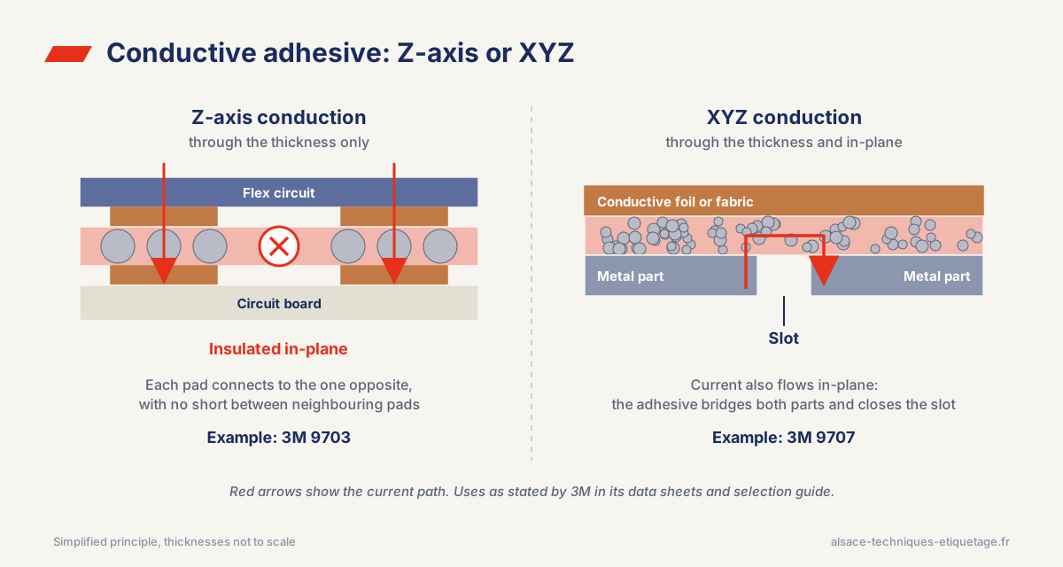
A conductive adhesive can conduct through its thickness only (Z-axis), or both through the thickness and in-plane (XYZ).
3M 9703 is a 0.05 mm transfer adhesive filled with silver particles. It conducts through the thickness and insulates in-plane. 3M positions it for grounding at precise locations without shorting adjacent traces. 9707, on the other hand, conducts in every direction, and 3M recommends it for shielding a slit or gap.
| Product | Thickness | Conduction | Z resistance | XY resistance | Stated use |
|---|---|---|---|---|---|
| 3M 9703 | 0.05 mm | Through thickness only | 0.01 ohm | Non-conductive | Localized grounding, interconnects without shorting |
| 3M 9707 | 0.05 mm | All directions | 0.03 ohm | 20 to 80 ohms | Slit and gap shielding, high frequency |
The same question applies to foil tape. With a non-conductive adhesive, the foil is separated from the surface by an insulating layer: it no longer grounds through its bonded face, and contact has to come from somewhere else, such as an overlap or a mechanical fastening. The adhesive is therefore chosen together with the grounding path.
How die-cutting affects shielding performance
Two parts cut from the same material can behave differently in the EMC test, depending on their shape and how they are fitted.
Slots and overlaps
According to Ron Brewer, an opening should stay below λ/50 and never exceed λ/20, λ being the wavelength of the frequency to block. At 1 GHz, the wavelength is 300 mm, so the rule gives 6 mm as a target and 15 mm as a maximum. A gap between two foils, a poorly overlapped corner or an overlong clearance cut-out is enough to create that slot. The geometry is therefore drawn with the problem frequency in mind. Without that figure, we cannot judge whether a clearance is acceptable.
Narrow bridges and small contact areas
A strip of foil a few millimeters wide, or an isolated contact tab, deforms easily, both at cutting and at application. A crease or a lifted edge creates a contact fault you cannot see. On these shapes, we work on radii, minimum bridge width and web direction before freezing the tool. We make our rotary dies in-house, so the tool is adjusted to the part rather than the other way round.
Gasket compression
A foam or fabric-over-foam gasket only conducts well within its compression range. Under-compressed, it makes poor contact; over-compressed, it pushes against the housing. The part thickness is therefore chosen from the actual gap between the two faces, including the tolerances of the plastic or metal parts, and not from the nominal dimension alone.
Laminating and insulation
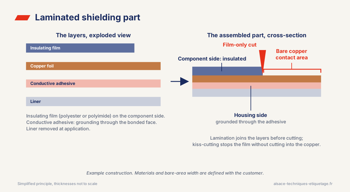
A shielding part often combines several layers: a foil and a conductive adhesive, or a foil covered with an insulating film on the component side to prevent short circuits. Laminating joins these layers before cutting, and kiss-cutting cuts one layer without cutting into the one below. An insulating area can therefore stop a few millimeters short of the edge, leaving bare metal where it has to make contact.
Delivery and application
A part applied by hand needs a pull tab and a liner that releases without stretching the adhesive. A part placed by a robot needs a consistent pitch, a suitable liner and a winding direction set in the specification. Our article on robotic placement of die-cut parts covers these points.
Galvanic corrosion at the housing interface
A shielding part puts one metal in contact with another. If the two are far apart in the galvanic series and an electrolyte forms at the interface, from humidity or condensation, the less noble metal corrodes. SSP notes that housings are most often aluminum or steel, while gaskets contain silver, nickel or copper. Corrosion raises contact resistance, and the shielding degrades over time even though it passed the test at the start.
A commonly cited rule, published by Carr Lane, limits the anodic index difference between the two metals according to the environment.
| Environment | Maximum difference |
|---|---|
| Harsh: salt, high heat, high humidity | 0.15 V |
| Indoor, no temperature or humidity control | 0.25 V |
| Climate-controlled indoor | 0.50 V |
The converter does not choose the housing metal. It does need to know it, along with its surface finish, to suggest a compatible foil metal or adhesive filler.
What to send us for a quote
With this information, we can propose the right material family in the first offer.
- The function of the part. Flat shield, gasket between two parts, grounding point or attachment of another element.
- The frequency or band to address, and the target test if you know it.
- The contact surfaces. Metal, surface finish, paint or metallized plastic.
- The expected grounding path. Through the bonded face, through an overlap or through a mechanical contact.
- The gap to fill for a gasket, with the tolerances of the surrounding parts.
- The environment. Temperature, humidity, vibration, service life.
- Application method and volume. Manual or automated, sheets or rolls, quantity per order.
For the first EMC tests, digital cutting produces parts without tooling, to ±0.1 mm depending on settings and material. Series production then moves to rotary die cutting, to a tenth of a millimeter on stable materials. For automotive electronics, we produce under IATF 16949 certification. ATE is also a 3M Preferred Converter.
Frequently asked questions
What is an EMI gasket?
A conductive gasket fitted between two parts of an enclosure to close the seam electrically. It can be made of conductive foam, fabric over foam, filled elastomer or metal. An untreated seam is often the largest opening in an enclosure.
Copper or aluminum foil tape for EMI shielding?
The choice depends on the shielding effectiveness you need, the metal it touches (to limit galvanic corrosion) and the adhesive available in each version. The data sheet of the selected product gives the shielding effectiveness and the contact resistance.
What is the difference between Z-axis and XYZ conductive tape?
A Z-axis adhesive conducts through its thickness only and insulates in-plane: it connects two faces without shorting neighboring traces. An XYZ adhesive conducts in every direction and is used, among other things, to close a slot or gap.
What is a fabric-over-foam gasket?
A gasket made of a soft foam core wrapped in conductive metallized fabric. It is compressed between two parts and suits doors, covers and connectors. TE gives a compression range of 10 to 70% for its own range.
How is shielding effectiveness measured?
In decibels, as the ratio of incident to transmitted field: 20 log (incident field / transmitted field). The value depends on frequency and test method, so it can only be compared at the same frequency and with the same method.