The part has been qualified for six years and placed by hand. The automation project starts, the arm holds two hundredths of a millimetre, and at start-up placement drifts by two millimetres. The robot is not the problem: the part was never designed to be picked by anything other than a hand.
3M puts it in its own automation handbook: you need to know whether die-cut parts will be applied manually or automatically before the tape is specified and converted.
Have your part reviewed for automated application
Nine steps, nine requirements on the part
Manual placement comes down to two gestures, peel and apply. The operator absorbs everything else with two hands and by eye, which a machine does not do.
| Step | What the part must allow for |
|---|---|
| 1. Presentation | A web on a continuous liner. Bulk parts rule out pick and place |
| 2. Separation | A consistent release force, and a cut that has not scored the liner |
| 3. Pick | A pick area whose face against the tool does not stick |
| 4. Transfer | Enough stiffness not to fold under acceleration |
| 5. Approach | A detectable target if vision alignment is used |
| 6. Application | A flat geometry, or a conformable tool for even pressure |
| 7. Dwell | This time counts against cycle time |
| 8. Release | A bond to the substrate already stronger than to the gripper |
| 9. Inspection | Contrast or a target showing the part is correctly placed |
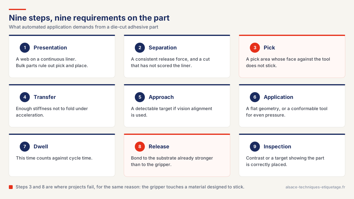
The real sequence of an automated placement, from web presentation to inspection. Click the diagram to enlarge.
Steps 3 and 8 are where projects fail, for the same reason: the gripper touches a material designed to stick.
The robot is the smallest contributor to placement error
When placement drifts, the reflex is to look at the arm’s datasheet, and that is rarely where the answer is. On datasheets citing ISO 9283, pose repeatability for a small-payload six-axis robot or a SCARA falls between 0.01 and 0.04 mm, and the manufacturers themselves state that this is an average across a small number of robots, varying with position in the working envelope, speed and arm configuration.
| Contributor | Order of magnitude |
|---|---|
| Arm repeatability | 0.01 to 0.04 mm per ISO 9283 |
| Die-cutting tolerance | Depends on process and material. Ask for it, then check it |
| Repeat pitch on the liner | A paper liner stretches under tension and the pitch drifts |
| Pick-up by the gripper | Not published. Part geometry drives it |
| Substrate fixturing | Often the real leading contributor, and the most overlooked |
| Vision alignment | Corrects upstream error, if there is a target to see on the part |
No standard publishes a placement tolerance for a die-cut adhesive part applied by robot. The only published figure we found comes from a label applicator manufacturer: plus or minus 0.5 mm at fixed speed, measured at the dispensing edge.
What keeps the part from sticking to the gripper
At step 8, the part’s bond to the substrate has to already exceed its bond to the tool. Peel and shear tell you nothing about this, since they measure joint strength after pressure has been applied. The useful property here is instantaneous tack, measured by loop tack under FINAT FTM 9 or ASTM D6195, two methods aimed at adhesives that form a measurable bond on contact, with no pressure applied. That is the regime of the contact between part and tool, and it is a value few people think to ask for.
| Part | Workable | Ruled out, and why |
|---|---|---|
| Thin flat film | Flat suction cup on the non-adhesive face | A pinch gripper marks the edge and distorts the film |
| Perforated film | Flow gripper, designed for air-permeable parts | A standard cup cannot seal |
| Open-cell foam | Needle gripper, designed for porous parts | Vacuum passes through the foam and the part crushes |
| Non-flat part | Bellows suction cup, or a conformable tool | A flat cup gives uneven pressure |
| Double-sided part | An adhesive-free pick zone, or a liner held to the last moment | Any direct pick on the adhesive |
What gets decided when the cutting tool is designed
The gripper can pick the part without touching the adhesive, provided the part was designed for it. Six parameters are set when the precision die-cutting tool is made. Once the tool exists, there is no catching up on them.
- The pull tab, extending the face stock beyond the adhesive zone
- The adhesive-free zone, where the geometry leaves no room for a tab
- The liner slit, which releases the part by opening rather than by peeling. See what the release liner changes in automated application
- The corner radius: a sharp corner catches the tool and starts an edge lift
- The matrix margin, which holds the web and lets the sensor tell two parts apart
- The registration target, if vision inspection is planned: it is drawn at the die stage
Placed is not bonded
A die-cut adhesive part does not reach final strength when the robot lets go. On an acrylic foam tape whose datasheet publishes the curve, the bond reaches about 50 % of ultimate strength after 20 minutes, 90 % after 24 hours and 100 % after 72 hours at room temperature. If the next station handles the part, size it on that intermediate strength, and a pull test at cell exit measures an intermediate value too.
That slow build also opens room to manoeuvre. One manufacturer states that final pressurization can take place up to 24 hours after the part is positioned: the robot places without applying full pressure, a separate station takes care of it later, and cycle time is no longer tied to dwell.
| Product | Published pressure | Temperature |
|---|---|---|
| 3M VHB 5952 | About 100 kPa, or 15 psi | Minimum suggested 10 to 15 °C, or 50 to 60 °F |
| tesa general guidance | Minimum 50 kPa, ideally 2 bar | Roughly 10 to 40 °C |
| tesa ACXplus 78XX | 20 N/cm², or 200 kPa | 15 to 35 °C |
| 3M 9495LE | Not published | Ideal 21 to 38 °C, or 70 to 100 °F |
So there is no universal application pressure: 50 to 200 kPa depending on the product, and one very common thin double-sided adhesive publishes none at all.
Converting a part already qualified for manual placement
Material and thickness usually stay put, so the bond performance your file already validated remains valid. What almost always moves is the packaging format, the outer geometry, the liner and the matrix margin. A different liner leaves the joint untouched but changes the article; a different die-cut geometry changes the part itself. Depending on your quality system, the consequence runs from a documentation update to a full PPAP submission, and the question belongs before the cell is ordered rather than after. Our page on our certifications and quality system sets out the framework.
One measurement is almost always missing from the file: the placement tolerance actually achieved by hand.
Have your part reviewed before you order the cell
We convert 700 raw materials and produce die-cut adhesive parts for automated adhesive assembly. We sell neither robots nor cells: our part of the job is the material, the die-cut geometry, the liner and the tolerances. Our plants are certified IATF 16949 since 2019, with an ISO 7 cleanroom area.
Send us the part drawing, the intended gripping method and the placement tolerance you need. We will tell you what holds as designed and what has to change before the cell is frozen.
Frequently asked questions
Is my robot’s repeatability enough to guarantee placement tolerance?
No. Pose repeatability published on datasheets citing ISO 9283 falls between 0.01 and 0.04 mm for a small-payload six-axis robot or a SCARA, but it is the smallest contributor in the chain. Add die-cutting tolerance, repeat pitch on the liner, pick-up by the gripper and fixturing of the substrate, which is often the real leading contributor.
How do I stop the part sticking to the gripper?
By making sure the gripper never touches the adhesive: a pull tab extending the face stock beyond the adhesive zone, an adhesive-free pick zone, or a liner slit that releases the part by opening rather than by peeling. These are set when the cutting tool is designed. Where picking on an adhesive face cannot be avoided, the property to look at is instantaneous tack, under FINAT FTM 9 or ASTM D6195, not peel adhesion.
Is the part bonded as soon as the robot lets go?
No. On an acrylic foam tape whose manufacturer publishes the curve, the bond reaches about 50 % of ultimate strength after 20 minutes, 90 % after 24 hours and 100 % after 72 hours at room temperature. If the next station handles the part, size it on the intermediate strength. These figures belong to one specific product and do not carry across to another construction.
Figures taken from published standards and public manufacturer datasheets. They are tied to the products and test conditions stated, and do not replace the datasheet for your own construction.
Sources
ISO 9283:1998, Manipulating industrial robots, performance criteria and related test methods
FINAT test methods (FTM)
ASTM D6195, standard test methods for loop tack
3M VHB Tape 5952 technical data sheet
3M Bonding Automation Handbook
tesa ACXplus application guide
Avery Dennison ALS labelling systems product information